Draw The Shear And Moment Diagrams For The Beam
Draw The Shear And Moment Diagrams For The Beam - Draw the shear and moment diagrams for the beam. Your solution’s ready to go! Let x be the distance measured from left end of the beam. The total load on the beam r a + r b = 12 × 5 = 60 k n. Skyciv beam tool guides users along a professional beam calculation workflow, culminating in the ability to view and determine if they comply with your region's design codes. Shear and moment diagrams and formulas are excerpted from the western woods use book, 4th edition, and are provided herein as a courtesy of western wood products association.
Divide the beam (of length l) into n segments. Draw the shear and moment diagrams for the beam. Web learn to draw shear force and moment diagrams using 2 methods, step by step. Web shear and moment equations and diagrams for beams. Also, draw shear and moment diagrams, specifying values at all change of loading positions and at.
Web draw the shear and moment diagrams for the compound beam using the graphical method. Web so in this post we’ll give you a thorough introduction to shear forces, bending moments and how to draw shear and moment diagrams. There are 3 steps to solve this one. 800n 500 n/m pa b 4 m 4m 4 m. Shear and bending moment diagrams.
Solved 8788. Draw The Shear And Moment Diagrams For The

In each problem, let x be the distance measured from left end of the beam. Shear and moment diagrams and formulas are excerpted from the western woods use book, 4th edition, and are provided herein as a courtesy of western wood products association. Draw the shear and moment diagrams for the beam. 20 kn 40 kn/m cl 150 kn m.
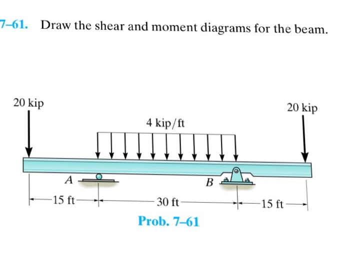
Solved 761. Draw the shear and moment diagrams for the
Web this is an example problem that will show you how to graphically draw a shear and moment diagram for a beam. Shear and moment diagrams and formulas are excerpted from the western woods use book, 4th edition, and are provided herein as a courtesy of western wood products association. Draw the shear and moment diagram for the beam. Web.
Draw Shear And Moment Diagrams For The Beam Zohal vrogue.co

Your solution’s ready to go! Web students also studied. There are 3 steps to solve this one. 20 kn 40 kn/m cl 150 kn m 8 m 3 m prob. 1) calculate support reactions 2).
Solved Draw The Shear And Moment Diagrams For The Beam, A...

In each problem, let x be the distance measured from left end of the beam. Determine all the reactions on the beam. Draw the shear and moment diagrams for the beam. Divide the beam (of length l) into n segments. Draw the shear and moment diagrams for the beam.
Solved 635. Draw the shear and moment diagrams for the

In each problem, let x be the distance measured from left end of the beam. Web shear and moment diagrams are graphs which show the internal shear and bending moment plotted along the length of the beam. 100% (2 ratings) share share. Here’s the best way to solve it. The total load on the beam r a + r b.
Solved Draw the shear and moment diagrams for the beam (a)

David roylance department of materials science and engineering massachusetts institute of technology cambridge, ma 02139 november 15, 2000. Draw the shear and moment diagrams for the beam. For reactions take moment about a ∑ m a = 0. View the full answer step 2. Your solution’s ready to go!
Solved Draw the shear and moment diagrams for the beam.

Your solution’s ready to go! There are 3 steps to solve this one. Draw the shear and moment diagrams for the beam. The diagram of the given beam is. Determine all the reactions on the beam.
Mechanics Map Shear and Moment Diagrams

David roylance department of materials science and engineering massachusetts institute of technology cambridge, ma 02139 november 15, 2000. The total load on the beam r a + r b = 12 × 5 = 60 k n. Web shear force and bending moment diagrams are analytical tools used in conjunction with structural analysis to help perform structural design by determining.
Draw the shear and moment diagrams for the beam.

Web shear and moment equations and diagrams for beams. 800n 500 n/m pa b 4 m 4m 4 m. Web so in this post we’ll give you a thorough introduction to shear forces, bending moments and how to draw shear and moment diagrams. Web express the internal shear and moment in the cantilevered beam as a function of x and.
Draw Shear And Moment Body Diagrams

Your solution’s ready to go! Shear and bending moment equations. David roylance department of materials science and engineering massachusetts institute of technology cambridge, ma 02139 november 15, 2000. Write shear and moment equations for the beam shown below. Web learn to draw shear force and moment diagrams using 2 methods, step by step.
Draw The Shear And Moment Diagrams For The Beam - Your solution’s ready to go! Draw the shear and moment diagrams for. Web this is an example problem that will show you how to graphically draw a shear and moment diagram for a beam. David roylance department of materials science and engineering massachusetts institute of technology cambridge, ma 02139 november 15, 2000. This page will walk you through what shear forces and bending moments are, why they are useful, the procedure for drawing the diagrams and some other keys aspects as well. Write shear and moment equations for the beam shown below. Shear and bending moment equations. The diagram of the given beam is. In each problem, let x be the distance measured from left end of the beam. Find the maxunum moments along the beam.
Web so in this post we’ll give you a thorough introduction to shear forces, bending moments and how to draw shear and moment diagrams. Web draw the shear and moment diagrams for the compound beam using the graphical method. Divide the beam (of length l) into n segments. Web shear force and bending moment diagrams are analytical tools used in conjunction with structural analysis to help perform structural design by determining the value of shear forces and bending moments at a given point of a structural element such as a beam. Determine the reactions at the supports using equilibrium equations.
Find the maxunum moments along the beam. Web express the internal shear and moment in the cantilevered beam as a function of x and then draw the shear and moment diagrams. Web our calculator generates the reactions, shear force diagrams (sfd), bending moment diagrams (bmd), deflection, and stress of a cantilever beam or simply supported beam. Web shear force and bending moment diagrams are powerful graphical methods that are used to analyze a beam under loading.
Here’s the best way to solve it. 100% (2 ratings) share share. Web 12k views 2 years ago statics.
Your solution’s ready to go! Web 12k views 2 years ago statics. Web the first step in calculating these quantities and their spatial variation consists of constructing shear and bending moment diagrams, \(v(x)\) and \(m(x)\), which are the internal shearing forces and bending moments induced in.
Web Shear Force And Bending Moment Diagrams Are Powerful Graphical Methods That Are Used To Analyze A Beam Under Loading.
Web learn to draw shear force and moment diagrams using 2 methods, step by step. Web 12k views 2 years ago statics. David roylance department of materials science and engineering massachusetts institute of technology cambridge, ma 02139 november 15, 2000. Determine the reactions at the supports using equilibrium equations.
For Reactions Take Moment About A ∑ M A = 0.
Note that the beam is fixed at a, pin connected at b, and supported by a roller at c. Web your solution’s ready to go! Shear and bending moment diagrams. Shear and bending moment equations.
View The Full Answer Step 2.
Web draw the shearing force and bending moment diagrams for the cantilever beam subjected to a uniformly distributed load in its entire length, as shown in figure 4.5a. Divide the beam (of length l) into n segments. Your solution’s ready to go! Draw the shear and moment diagrams for the beam.
Neglect The Mass Of The Beam.
Web calculate the reactions at the supports of a beam, frame and truss. Web express the internal shear and moment in the cantilevered beam as a function of x and then draw the shear and moment diagrams. Web shear and moment equations and diagrams for beams. Let x be the distance measured from left end of the beam.